MIPS Actus
Maintenance inside the joint
MIPS says its Actus chip can drive a robot joint's motor and also run models that predict when maintenance is due, and no independent measurement was found.
Chips · Checked 13 Nov 2026 · 8 sources · 9 min
A maintenance technician who has looked after the same machine for years can often tell it is going wrong before any alarm does. The gearbox sounds different, or its motor is drawing more current than it did the winter before. Catching that slow change early is called predictive maintenance, and it is now done with sensors that watch a machine's vibration, temperature and current, so the repair can be planned and not made after a breakdown.
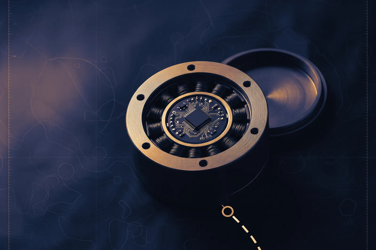
A compact robot joint packs motor, gears and electronics into one small housing, with little room for anything extra. The chip that drives that motor is already measuring it, though, thousands of times a second. On 9 November 2026 MIPS, a GlobalFoundries business, published details of its Actus reference platform, a single chip for compact robot joints that combines motor control, networking inside the robot and the running of trained models on the spot. A trained model is a program whose behaviour was learned from recorded examples and not written out by hand. MIPS says models for predictive maintenance can run "on the same chip that drives the motor." Every performance figure published for Actus comes from MIPS, and no independent measurement was found.
Start with why such a chip has to measure anything. Suppose the joint is the elbow of a robot arm, bending to lift a part. Inside is an electric motor of the type called an AC motor: a ring of fixed wire coils around a rotor, the part that turns, which carries a magnetic field. Current through the coils makes a second field, and the rotor is pulled round as its field tries to line up with theirs. How hard it is pulled depends on the angle between the two, as with a spanner on a nut. Push at a right angle to the handle and the nut turns. Push along the handle and nothing turns, however hard you push. In the motor the rotor's field is the handle, and only the part of the coils' field that pushes across it produces turning force.
The part that lies along the rotor's field is not wasted the way a push along a spanner is, and there the comparison stops. It strengthens or weakens the magnetism inside the motor. So a controller has two things to manage, turning force and magnetism, and in the currents it can measure the two are mixed together. One method of separating them is called field-oriented control. A Texas Instruments application report describes it as using "mathematical transformations in order to decouple the torque generation and the magnetization functions" of an AC motor, torque being the engineer's word for turning force. The second of its two steps, the Park transformation, re-describes the current as it would look from a seat turning with the rotor's field. That takes the sine and cosine of the angle of the rotor's field, the functions of school trigonometry, worked out afresh as the rotor turns.
Knowing what current it wants, the chip has a blunt tool for making it flow. The switches that feed the coils are either fully on or fully off. To deliver something in between, a switch is turned on for part of a short interval and off for the rest, and the coil smooths the pulses toward their average. This is pulse-width modulation, PWM, which sets the motor's voltage by the timing of switching edges, the instants at which a switch turns on or off. The chip generates the switching signals. MIPS's Actus-1 block diagram shows no power stage, the transistors that carry the motor's current and the circuits that drive them, so separate power electronics are implied.
None of this is done once. The rotor moves and the load changes, so the chip runs a loop: measure the currents in the coils, find the rotor's angle, do the trigonometry, decide the new voltages, set the switch timings, begin again. The worked example in the Texas Instruments (TI) report uses a rate of 10 kHz, which is 10,000 passes a second, or one pass every 100 microseconds (1 second divided by 10,000). A microsecond is a millionth of a second. Every pass has to finish on time, because a late answer aims the coils at where the rotor used to be.
The 16x claim covers one step
On Actus the loop runs on two processor cores, each a complete processor within the chip, of a MIPS design called the Atlas M8500. The release says they have dedicated acceleration for the trigonometry of field-oriented control. That arithmetic is slow done the usual way: a processor adds in a single step, but ordinary software has to work a sine out in a run of smaller steps. The release's first figure is "more than 16x the performance of standard trigonometric libraries on field-oriented control algorithms", a library being a stock collection of such software.
The release does not say which library that was, which processor it ran on or what work it was doing, and MIPS describes no test setup or measuring party for any of its figures. A speed-up is a ratio, and whoever publishes it chooses what it is measured against: beside a slow enough routine on a slow enough processor, almost any multiple can be had. The figure may be fair. With the other half of the comparison unnamed, nobody outside MIPS can repeat it.
Even taken at its word, the figure speeds up one step of the loop, and what that is worth depends on how large the step was. Suppose, with numbers invented for the sum, that the elbow's chip needs 100 microseconds to work through one pass and that the trigonometry accounts for 16 of them. Make the trigonometry 16 times faster and it takes 1 microsecond. The other 84 are untouched, so the pass takes 85, which is 15 fewer than 100. Had the trigonometry filled nearly all of the pass, the same gain would have cut the pass to a fraction of its length. The split has to be invented because MIPS does not give trigonometry's share of the loop's time, so the figure's effect on the loop's rate is unknown.
The release gives no loop time either. The page for the M8500 core alone claims a "sub -10μs control loop", a pass in under 10 microseconds. That would mean more than 100,000 passes a second (1 second divided by 10 microseconds), ten times the rate in TI's example.
The release's second figure belongs to the loop's last step. MIPS claims PWM resolution that is "100-picosecond-class". Resolution is the smallest step by which a switching edge can be moved, and a picosecond is a millionth of a microsecond. Suppose the elbow's switches go through one on-and-off cycle in each 100-microsecond pass. That interval is 100 million picoseconds long, so an edge that moves in 100-picosecond steps has a million places to land (100 million divided by 100), and the more places it can land, the more finely the average voltage can be set. TI gives the step of its own C2000 chips as "on the order of 150 ps", meaning picoseconds, and says it varies with manufacturing process, temperature and voltage. The two figures are of the same order of magnitude. MIPS does not define "class", and gives no temperature or voltage at which its figure holds.
The smallest step of a switching edge, as each maker states it
Two figures of the same order, one with its conditions
| MIPS Actus | TI C2000 | |
|---|---|---|
| The step | "100-picosecond-class" | "on the order of 150 ps" |
| What it depends on | Not given: no temperature or voltage, and "class" is not defined | Varies with manufacturing process, temperature and voltage |
What the loop already knows
Go back to the technician who noticed a motor drawing more current than it used to. That number is already inside the loop. On every pass the chip measures the current in the coils and finds the rotor's position, and the Park transformation hands it the turning part of the current as a value of its own. A joint that has begun to stiffen needs more turning force for the same movement, and so more of that current.
MIPS says a vector unit beside the control cores is what lets models for predictive maintenance run on the chip, along with models for sensor fusion, the combining of several sensors' readings into one estimate. A vector unit is a processor built to carry out one operation on a whole row of numbers at once. MIPS calls this one a 512-bit unit, and 512 bits is the width of the row. A stream of sensor readings is a row of numbers, and a trained model is run by multiplying and adding rows of them.
The release calls the design an "open RISC-V platform". RISC-V is an open standard for the set of instructions a processor understands, and the control cores follow it. The vector unit, though, comes from another MIPS line, ARC, which the ARC VPX family page describes as "based on an enhanced ARCv2DSP instruction set", with 512-bit vectors belonging to its VPX5 parts. Software built for one instruction set does not run on another. If Actus uses a standard VPX5, its vector unit is not RISC-V.
The release says software teams can begin on a virtual platform, a simulation of the chip, "before silicon arrives", and then move to an Actus-1 evaluation board. Whether that board carries the final chip, a test chip or a reprogrammable chip set up to imitate it is not stated. No MIPS page gives a price, part number, ship date or license, and the Actus product page offers a contact form in place of an order or download link. No source names a robot, a robot maker or a customer that uses Actus, and none gives a date for it in a production robot.
On 5 November 2026 Renesas, another chip company, announced the RZ/T2N, with motor control and industrial Ethernet on one chip, and stated that the chip and its evaluation board are available. No source compares it with Actus, and MIPS gives no clock, memory or power figure to set against it.
If the vector unit runs maintenance models beside the motor loop as MIPS describes, those models would sit next to the joint's current and position signals. The public material names no sensor to be fused and no maintenance model, and gives nothing to build one against: no model format, no programming tools for the vector unit, no memory budget, no sample rate and no example.
Check it yourself
- Open the MIPS press release and confirm the date, the 16x and 100-picosecond wording and the sentence about the vector unit and "the same chip that drives the motor."
- Open the Actus product page and look for a price, a part number or an order link, to confirm that it offers a contact form in their place.
- Open the Actus-1 block diagram and confirm that it shows timers and PWM but no power stage.
- Open the Atlas M8500 page, find the "sub -10μs control loop" wording, and divide 1 second by 10 microseconds to get the 100,000 passes a second.
- Read the ARC VPX family page to confirm the ARCv2DSP instruction set and that 512-bit vectors belong to the VPX5 parts.
- Open the Renesas release and confirm that it states the RZ/T2N and its evaluation board are available.
- Read the TI C2000Ware calibration page for the step "on the order of 150 ps" and what TI says it varies with.
- Read section 3.7 of TI's field-oriented control report on the Park transformation, and find the 10 kHz rate in its worked example.
Sources
- MIPS Unveils Actus Platform for Precise, Secure Robotic Motion Control. MIPS, 9 November 2026.
- Texas Instruments application report SPRABQ0 on field-oriented control. Texas Instruments, October 2013.
- MIPS Actus-1 block diagram. MIPS.
- MIPS Atlas M8500 product page. MIPS.
- TI C2000Ware calibration libraries guide. Texas Instruments.
- MIPS ARC VPX DSP family page. MIPS.
- MIPS Actus product page. MIPS.
- Renesas release on the RZ/T2N MPU. Renesas Electronics, 5 November 2026.